Seasonal cooling devices are aimed at freezing of thawed ground and cooling of plastic frozen ground in the foundation of constructions with or without ventilated undergrounds around transmission tower and pipelines support, along railroad embankments and highways for the purpose of improving their bearing capacity and prevention of pile popping in areas of permafrost distribution. You can learn more about the technology of ground thermostabilization on this page of the website.
Тoday the problem of ground simulation of seasonal cooling devices thermal influence can be solved effectively in Frost 3D software package. The following data is necessary for this purpose:
1.Meteorological data (tab. 1): air temperature, wind speed and snow cover thickness;
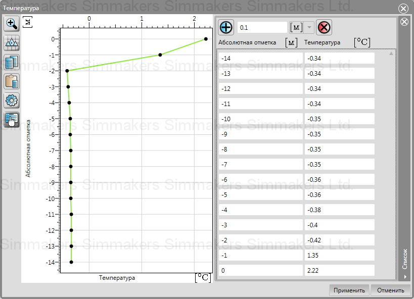
2.Engineering-geological structure of ground (tab.2) and its initial temperature on calculation start date (tab. 3);
3.Thermophysical properties of geological layers (tab. 4): thermal conductivity and volumetric heat capacity in a thawed and frozen state, graph of unfrozen water, temperature of phase transition, ground density;
4.Technical characteristics of thermosyphon (tab. 5).
Тab. 1 – Climatic data
| Parameter | Month | |||||||||||
| 1 | 2 | 3 | 4 | 5 | 6 | 7 | 8 | 9 | 10 | 11 | 12 | |
| Air temperature, оС | -27,3 | -24,3 | -16 | -5,3 | 4,8 | 13,2 | 16,4 | 12,5 | 4,1 | -5 | -19,5 | -26,8 |
| Wind speed, m/s | 2,3 | 2,1 | 2,1 | 2,4 | 2,4 | 2,1 | 1,8 | 1,8 | 1,9 | 2,3 | 2,3 | 2,4 |
| Snow cover height, m | 0,28 | 0,31 | 0,32 | 0,27 | 0 | 0 | 0 | 0 | 0 | 0,14 | 0,19 | 0,25 |
| Snow density, kg/m3 | 275 | 300 | 320 | 330 | 0 | 0 | 0 | 0 | 0 | 180 | 220 | 240 |
Tab. 2 – Ground thickness on each well
| Geological layer thickness, m | ||||
| Name of geological layer | Well 1 | Well 2 | Well 3 | Well 4 |
| EGE-1 | 1,5 | 1 | 1,9 | 0,7 |
| EGE-2 | 1,9 | 1,2 | 3 | 1,5 |
| EGE-3 | 0,8 | 1,2 | 1 | 2 |
| EGE-4 | 2,4 | 2 | 1 | 4 |
| EGE-5 | 3 | 3,8 | 2,5 | 1 |
| EGE-6 | 2,7 | 2 | 4 | 4 |
| EGE-7 | 1,7 | 1,8 | 0,6 | 0,8 |
Tab. 3 – Temperature distribution in ground depth on 01.10.2016
| Depth, m | Тemperature, оС |
| 0 | 2,22 |
| 1 | 1,35 |
| 2 | -0,42 |
| 3 | -0,40 |
| 4 | -0,38 |
| 5-6 | -0,36 |
| 7-10 | -0,35 |
| 11-14 | -0,34 |
Fig. 1 – Position of geological wells in the 2D Editor of the software package
Tab. 4 – Thermophysical properties of ground
| Name of material parameter | Name of material | ||||||
| EGE-1 | EGE-2 | EGE-3 | EGE-4 | EGE-5 | EGE-6 | EGE-7 | |
| Temperature, оС | Temperature distribution in ground depth on 01.10.2016 | ||||||
| Volumetric heat capacity of thawed ground MJ/(m3∙оС) | 2,78 | 3,17 | 3,17 | 2,31 | 2,78 | 2,39 | 2,31 |
| Volumetric heat capacity of frozen ground, MJ/(m3∙оС) | 2,06 | 2,41 | 2,41 | 2,14 | 2,26 | 2,08 | 2,14 |
| Thermal conductivity of thawed ground, W/(m∙оС) | 1,91 | 1,57 | 1,57 | 1,62 | 2,26 | 2 | 1,62 |
| Thermal conductivity of frozen ground, W/(m∙оС) | 2,14 | 1,8 | 1,8 | 1,74 | 2,62 | 2,2 | 1,74 |
| Total moisture content of ground, unit fraction | 0,14 | 0,29 | 0,57 | 0,27 | 0,23 | 0,21 | 0,18 |
| Dry ground density, kg/m3 | 1550 | 1450 | 1030 | 1470 | 1590 | 1630 | 1710 |
| Plasticity index, lp | 0,01 | 0,10 | 0,10 | 0,05 | 0,01 | 0,01 | 0,6 |
| Temperature of phase transition, оС | -0,1 | -0,21 | -0,26 | -0,31 | -0,24 | -0,27 | -0,32 |
Tab. 5 – Technical characteristics and scheme of thermosyphon
| Condensator |
1 – condensator part; 2 – transport part; 3 – evaporative part |
|
| Diameter, mm | 34 | |
| Length of overground part, m | 1,5 | |
| Finning of condensator | ||
| Type of finning | crosscut, circular | |
| Diameter of fins, mm | 70 | |
| Fin pitch, mm | 2,5 | |
| Number of fins, pcs | 300 | |
| Thickness of fins, mm | 1 | |
| Material of fins; thermal conductivity, W/(m∙оС) | Aluminium; 203,5 | |
| Evaporator (without inserts) | ||
| Diameter, mm | 34 | |
| Length of underground part, m | 13 | |
| Length of thermal insulated part, m | 2 | |
It is necessary to calculate ground thermal condition at influence of seasonal cooling device within 5 years of its usage from 01.10.2018 to 01.05.2024.
Geological-lithological ground structure consisting of various engineering-geological elements (EGE) is restored on the basis of several engineering-geological wells by means of methods of three-dimensional interpolation.
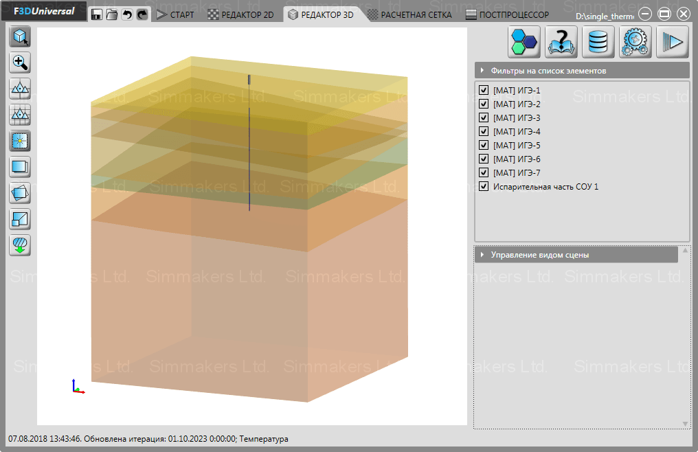
The dimensions of the simulation area need to be taken so that the annual course of temperature doesn’t influence thermal condition of ground more deeply than temperatures of zero thermal economies. It is also necessary to consider thermosyphon influence and to distance side and lower borders of computational domain so that at this distance there was no its influence on ground thermal distribution. On the basis of these considerations, it was decided that the computational area of 25х25х30 meters would be taken (fig. 2). Since the geological structure of ground is known only up to 14 meters from the ground surface, it was decided that the last layer of ground would be increased (EGE-7) by 16 meters.
Fig. 2 – Created 3D computational domain
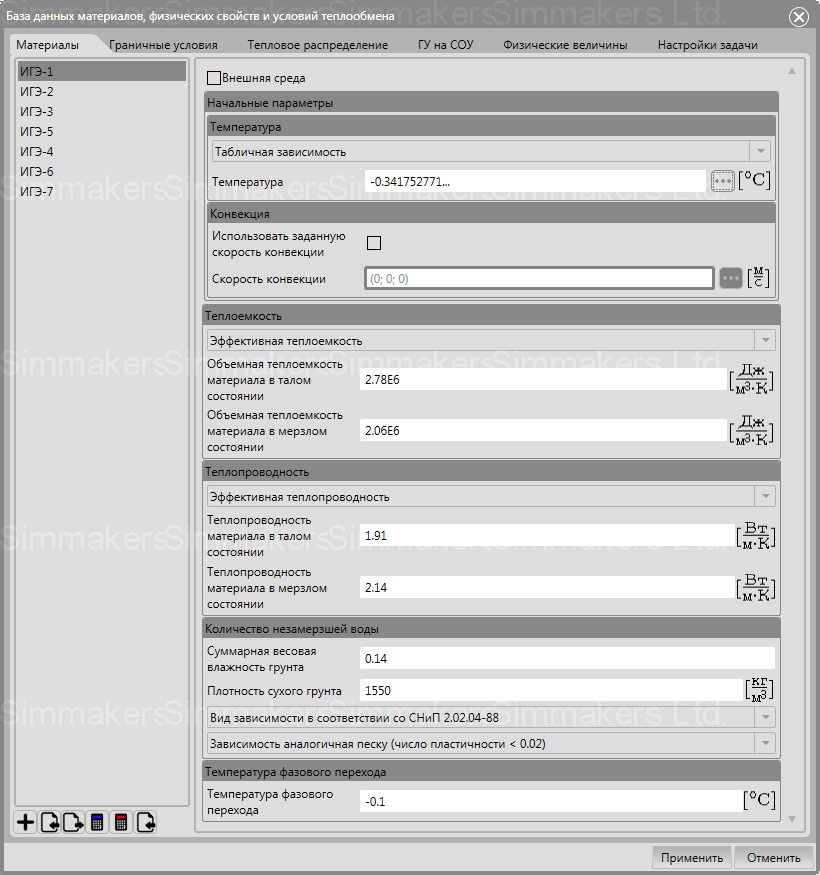
Thermophysical properties of ground (tab. 3) are set in the software base (fig. 3), then you set thermophysical properties of each ground layer as well as the initial temperature along the whole depth of the computational domain (fig. 4).
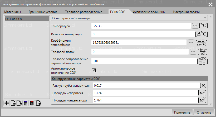
For the subsequent simulation of cooling device influence on ground, it’s necessary to create and locate it in three-dimensional computational domain (fig. 5). Thermosyphon operation is described in the corresponding section of the software database.
In the database it is necessary to set the following values for thermosyphon operation description:
- Annual course of air temperature in the considered area.
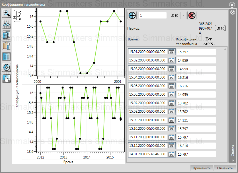
- Coefficient of air and condensator heat exchange which defines convection heat transfer of the condensator. This coefficient can be calculated in Frost 3D solver of heat exchange conditions depending on design features of the condensator (fig. 7, 8).
- Difference of temperatures between condensator and evaporator is total temperature losses due to pressure difference, particularly, hydrostatical pressure in medium and upper layers of boiling cooling agent.
- Thermal resistance of thermosyphon characterizes additional temperature losses by transfer of heat from ground to the evaporator. The value of this parameter is defined from experimental temperature values on the evaporator and the condenser at a certain value of thermal load of cooling device.
- Design data of seasonal cooling devices:
- pipe radius of the evaporative part;
- the area of the evaporative part, contacting with ground;
- the area of fins of a condensator part, contacting with the environment.
Fig. 6 – Parameter setting for description of seasonal сooling device operation
Boundary conditions setting on the computational domain border
After the creation of three-dimensional model of computational domain, it is necessary to set the following boundary conditions on its borders which need to be created in the database:
- On the upper border of computational area it is necessary to set a 3 type boundary condition (fig. 9) where it is necessary to enter periodically time changeable air temperature (fig. 10) and coefficient of heat exchange (fig. 11). The coefficient of heat exchange of ground with air is calculated from wind speed. In cold season the heat exchange coefficient is also influenced by height of snow cover (fig. 12) and its density (fig. 13) which values can be set in the corresponding parameters of a boundary condition.
- On a side surface the thermal stream equal to zero is set as side surfaces are at rather remote distance from seasonal cooling device and it is supposed that ground temperature behind side border of computational area will correspond to temperature in settlement area at its border.
- On the lower border of computational area the constant temperature of permafrost ground, equal to -0,34 C is set since the lower border is situated on sufficient distance from sources of heat and it won’t be influenced by seasonal cooling devices work.
Fig. 9 – Boundary condition setting on the ground surface
Simulation results
Thermal analysis of computer model was made for 5 years, beginning with October 1, 2018 till May 1, 2024. The influence of the seasonal vertical device on ground is shown below in the form of color distribution of temperature and unfrozen water content in the simulation area on the 15th day of each month (fig. 14, 15).

Fig. 14 – Temperature ground condition in the cross section of the simulation area in the location of seasonal cooling device

Fig. 15 – Unfrozen water content in ground in the cross section of simulation area in the location of seasonal cooling device
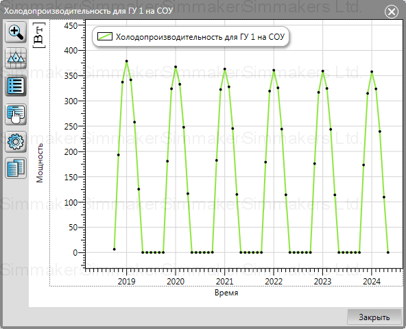
On the basis of the received results of calculation, the scheme of refrigerating capacity of all surface of evaporative part of the seasonal cooling device (fig. 16) is automatically created. This scheme can be used for assessment of efficiency of the thermosyphon in the considered climatic conditions.
Fig. 16 – Automatically created scheme of refrigerating capacity of seasonal cooling device for the whole time of simulation


